NOTE. If no testing chamber is used proceed to step 5.
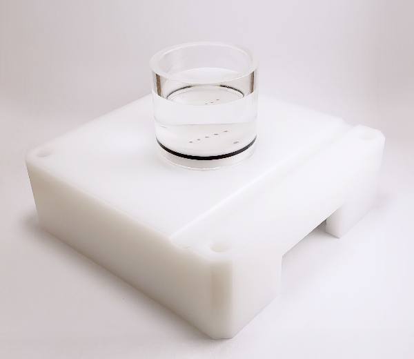
1. Completely screw the sample holder into the testing chamber and place the sample over it. If applicable, center the sample relative to the holder and rotate it in such a way that its orientation will approximately correspond to that of the corresponding surface positioning template image when seen by the technician in front of the testing chamber. Using a black marker, draw a mark on the top of the sample holder that will be used for the repositioning of the sample over the holder.
2. Remove the sample and unscrew the sample holder.
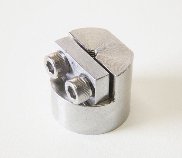
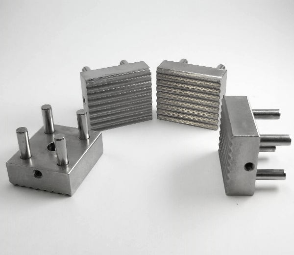
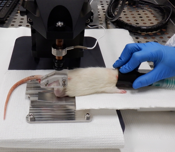
3. Depending on the sample type, a sample has to be attached to the sample holder following an appropriate method, either with screws and/or cyanoacrylate glue (recommended: Loctite 4013).
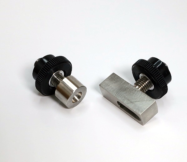
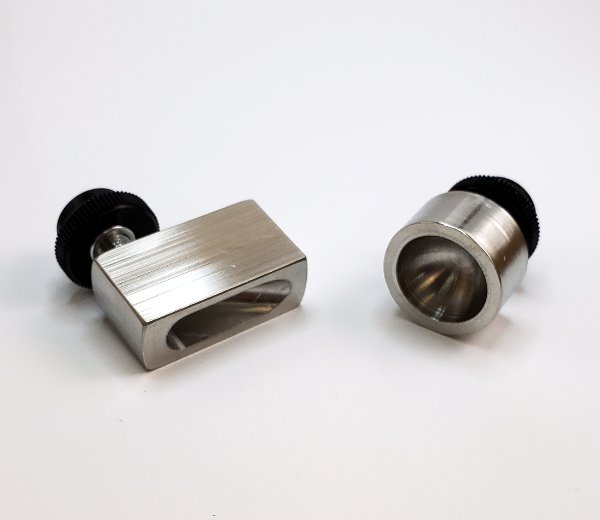
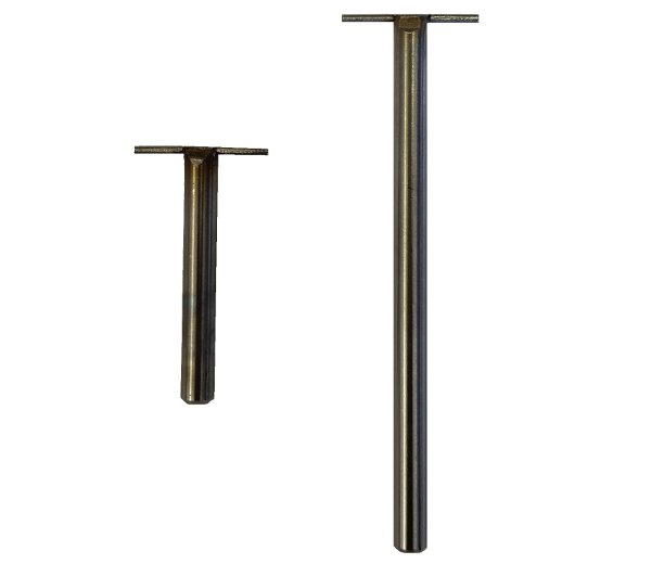
“Screws” method: In the case of sample holder (a – see Figure 1a), place the flat sample side in firm contact with the sample holder. Secure it with at least 2 screws from the bottom side. Make sure that the screws remain at least 1 cm away from the surface. In the case of sample holder (b – see Figure 1b), place the flat sample side in firm contact with the sample holder. Secure it from the periphery using its 6cone-ended screws. In the case of sample holder (c – see Figure 1c), place the sample in the middle. Secure it with its 2 screws.
“Glue” method: In the case of any sample holder with a flat portion (see Figure 1), make sure that the bottom surface of the sample and the flat portion of the sample holder are dry to ensure a good adherence. In the case of articular surfaces, apply the glue on the sample bottom (the bony part) and be careful not to touch the cartilage surface. If by mistake the glue touches the sample, try to clean the surface by using a flux of PBS, and report approximately the touched area in the laboratory book. The glued sample should be maintained for at least 1 minute to ensure a good adherence.
4. Screw the assembly into the testing chamber.
5. If required, create two reference points on the surface as per the “Calibration of the sample” section. If required, measure the horizontal distance between the references with a calibrated caliper and report the value (ideally, at a location specified in an associated protocol).
6. Adjust the position of the camera and its focus in such a way that the sample’s surface occupies the maximum space in the live camera feed while remaining completely visible by keeping a margin of about 5% at the 4 sides (right, left, up and down) to accommodate an eventual water refraction compensation, if applicable. It is recommended to use an appropriate surface positioning template to facilitate eventual mapping comparison between samples.
6.1. Choose “Import .map” in “File” of the menu bar.
6.2. Select the corresponding surface positioning template (*.map) and boundaries will be displayed by a closed contour (solid line) in the camera feed.
6.3. Adjust the position of the camera and its focus in such a way that the sample’s surface boundaries fit those of the surface positioning template.
7. Superimpose a position grid to the sample image. Positions could be added one by one according to a snapping grid (aligned) or anywhere on the sample. Also, positions could be imported through a previously created .map file. Note that it is important to edit/select a sub-surface in the Sub-SurfaceID field before adding a position in order to assign the position to a sub-surface.
7.1 If applicable, choose “Import .map” in “File” of the menu bar and select the corresponding position grid and the positions will be displayed by a circled marker in the camera feed.
7.2 If applicable, choose “Grid” in “View” of the menu bar to display a grid of snapping dots in the camera feed.
7.3 Edit the Sub-Surface ID field as defined in the associated protocol.
7.4 Choose “Add Positions” in “Edit” of the menu bar and click in the camera feed to add positions at each location of interest on the sample sub-surface.
7.5 If necessary, choose “Delete Positions” in “Edit” of the menu bar and click in the camera feed at each position that is not overlaid on a location of interest on the sample sub-surface and the position will be deleted from the camera feed.
7.6 Repeat steps 7.3 to 7.5 for each sub-surface of the sample.
8. If required, create the specific boundary of the sample sub-surfaces in order to refine the outline of the mapping surface for this specific sample (using at least 30 boundary points). If needed, surface boundary layer from the positioning template can be deleted first. Note that this step is important for the interpolation of characterization values to the boundary to obtain a complete mapping of the sample surface. Note that it is important to edit/select a sub-surface in the Sub-SurfaceID field before adding a boundary in order to assign the boundary to a sub-surface.
8.1. Choose “Boundary” in “View” of the menu bar to see boundaries in the camera feed.
8.2. Edit the Sub-Surface ID field as defined in the associated protocol.
8.3. Choose “Add Boundary” in “Edit” of the menu bar and click in the camera feed to define the boundary along the sample sub-surface and a closed contour will be created.
8.4. If necessary, choose “Delete Boundary” in “Edit” of the menu bar and click in the camera feed at a boundary point along the sample sub-surface and the closed contour will be reshaped consequently.
8.5. Repeat steps 8.2 to 8.4 for each sub-surface of the sample.
9. If required, add reference indicators on the two reference marks previously created at step 5.
9.1. Choose “Reference 1 (red)” in “Edit” of the menu bar and click in the camera feed at the first reference mark.
9.2. Choose “Reference 2 (blue) in “Edit” of the menu bar and click in the camera feed at the second reference mark.
10. Create this blank “Filename.map” file, where “Filename” is standardized filename format that it is recommended to define in an associated protocol (refer to Appendix I for a recommended file naming convention). When filename standardization is not necessary, any name can be used as “Filename”. Choose “Create .map” in “File” of the menu bar and all positions, boundaries and references displayed in the camera feed will be saved in the .map file and a snapshot image “.jpg” of the camera feed will be saved in the same folder.
Mapping Toolbox – Sample Holders